A 4V210-08 that will not shift, exhausts continuously, moves a cylinder the wrong way, or overheats needs a methodical separation of electrical, pneumatic, and mechanical faults. By checking the port logic, energised coil voltage, pilot air, exhaust path, and actuator circuit in order, you can identify the failed stage before replacing the valve.
Key takeaways
- Confirm the body marking says 4V210-08, not 4V220-08.
- Test the DC24V coil electrically instead of relying on a clicking sound.
- Check pilot air, exhaust flow, and cylinder movement as separate faults.
- Specify port size, voltage, function, and thread before ordering a replacement.
Start with the Port Map and the Exact Valve Version
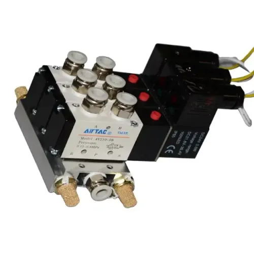
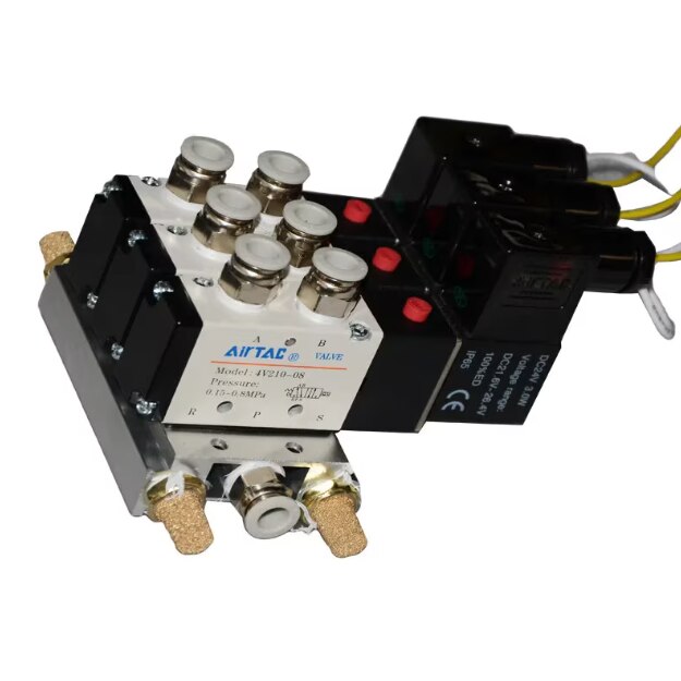
Read the valve body marking before tracing any fault: it should identify a 4V210-08, not a 4V220-08. The 4V210-08 is a 5-port, 2-position, single-solenoid valve with spring return; 4V220-08 is double-solenoid and behaves differently. “08” normally denotes 1/4-inch threaded ports.
Confirm the installed version with this checklist:
- Match the marking to 4V210-08 and verify the coil voltage and connector.
- Identify port 1/P as the compressed-air supply.
- Connect 2/A and 4/B to the cylinder’s two ports.
- Leave 3/R and 5/S as exhaust ports, fitted with suitable mufflers.
- Check the thread form, mounting or manifold arrangement, and seal compatibility before calling it a match.
- De-energise the coil and observe the spring-return cylinder direction; energise it and confirm the opposite direction.
A and B tubing swapped at the valve produces reversed cylinder movement, often mistaken for one of the 5 port solenoid valve problems. A blocked muffler or restricted exhaust can also make a correctly tubed valve move slowly.
For anyone searching air t ac 4v210 08 valve for problems in bangalore, verify the port map on the actual body rather than relying on a similar-looking photograph or supplier label. A correct model with inadequate pilot pressure still will not shift reliably.
Use a DC24V Electrical Test Instead of Listening for a Click
Start with the load-side measurement: command the PLC output on and measure DC voltage directly across the 4V210-08 coil terminals.
A 24 V reading at the PLC or relay does not prove that the coil receives 24 V; long cables, corroded terminals, weak relay contacts, undersized conductors, and a poor common return can create a voltage drop.
Use this sequence for 4v210 08 troubleshooting:
- Measure the power supply at the valve under load. Confirm approximately 24 VDC, the correct polarity, and a secure common connection.
- Measure the PLC output at its terminal, then repeat the measurement across the coil. No voltage at both points indicates a supply, fuse, interlock, or PLC-output problem; voltage at the PLC but not the coil indicates wiring, connector, relay, or common-return failure.
- Inspect the plug, pins, cable, and indicator LED. An LED can show command voltage, but it does not prove that the coil produces a magnetic field.
- Isolate power and measure coil resistance. An open reading indicates a broken coil; a near-zero reading indicates a shorted coil. Compare the result with the manufacturer’s specification.
- Press the manual override briefly. If the cylinder shifts, the air circuit and actuator can function, leaving the coil, wiring, PLC output, interlock, or supply under suspicion.
If the manual override also fails, do not condemn the coil immediately. Check supply pressure at the valve, port 1/P, ports 2/A and 4/B, exhaust ports 3/R and 5/S, blocked mufflers, and contamination.
Moisture, pipe scale, PTFE fragments, or a stuck spool can mimic dc24v pneumatic valve issues; a spring-return valve should return when power is removed.
Separate Pilot-Air, Exhaust, and Cylinder Faults
Isolate the fault by testing the valve’s air path separately from the cylinder and load. A coil that energises proves only that the solenoid receives a command; it does not prove that the spool shifts or that air can move through the circuit.
- Check pressure at port 1/P while the valve is commanded. A typical 4V210-08 operates around 0.15–0.8 MPa; pilot pressure below the valve’s minimum can leave an energised spool stationary.
- Confirm the port logic: 1/P is supply, 2/A and 4/B connect to the cylinder, and 3/R and 5/S exhaust. A swapped hose reverses movement, while a blocked muffler or exhaust line slows or stops the stroke.
- Press the manual override briefly. If the cylinder moves, inspect the coil connector, PLC output, voltage under load, and electrical interlock. If it does not move, inspect pressure, porting, contamination, exhaust restriction, and spool movement.
- Test the cylinder without its load where safe. Binding guides, a damaged seal, misalignment, or an overloaded rod can imitate valve failure.
- Remove trapped pressure before dismantling. On spring return, the spool should return when power is removed; failure points to a stuck spool, damaged spring, blocked exhaust, residual pressure, or incorrect plumbing.
This sequence separates 4v210 08 troubleshooting from general 5 port solenoid valve problems: prove supply and exhaust first, then the valve, then the cylinder and load.
Match Each Symptom to Its Likely Fault
Constant exhaust from 3/R or 5/S points to a stuck spool, damaged internal seal, blocked pilot exhaust, or incorrect tubing. If air escapes from a fitting or port, tighten the connection only after checking for a cracked tube, damaged thread, or failed seal.
| Symptom | Check first | Likely fault |
|---|---|---|
| Constant exhaust | Spool position, exhaust mufflers, port map | Contamination, seal failure, blocked exhaust, or incorrect plumbing |
| Wrong-direction movement | 2/A and 4/B tubing, cylinder ports | Swapped work lines or incorrect cylinder connection |
| Slow actuation | Pressure at 1/P, filter, FRL, tubing, load | Pressure drop, saturated filter, restricted muffler, undersized tube, or excessive load |
| Coil overheating | Coil marking, measured voltage, ambient temperature | Wrong voltage or current type, overvoltage, continuous duty fault, or excessive heat |
| Buzzing | Voltage stability, connector, coil seating | Low voltage, AC/DC mismatch, loose armature, or contamination |
| Intermittent operation | PLC output, common, polarity, terminals, supply pressure | Corrosion, loose wiring, unstable pressure, sticking spool, or condensate |
| Air leakage | Fittings, seals, valve body, exhaust | Damaged seal, cracked tube, loose fitting, or internal spool leakage |
For Airtac solenoid valve faults and dc24v pneumatic valve issues, check these points before replacing the valve:
- Measure 24 VDC at the coil while energised; inspect LED, connector, common, polarity, and coil resistance.
- Remove power and confirm the spring returns the spool; test the manual override only after isolating pressure.
- Compare pressure at 1/P with pressure at the valve during movement, then drain condensate and inspect the filter. Monsoon humidity and hot compressor rooms can expose corrosion or coil-temperature faults.
Specify the Replacement Without Repeating the Failure
Confirm the installed valve’s identity before ordering: it must be a 4V210-08, 5-port, 2-position, single-solenoid valve with spring return. A 4V220-08 is a double-solenoid model; substituting it changes the fail position and control logic.
1. Match the port specification: verify the “08” 1/4-inch thread designation, then confirm the thread form, such as BSP or NPT, against the existing manifold and fittings. A matching port size with the wrong thread will leak or damage the connection.
2. Match the electrical specification: read the coil marking for voltage and current type, such as DC24V or AC. Check the connector style, LED, polarity, and power rating. Do not infer the coil voltage from the machine’s nominal control voltage; a wrong coil can overheat or fail to shift.
3. Match the pneumatic duty: confirm the required operating-pressure range, flow capacity, seal material, and compatibility with the plant’s oil and air treatment. A saturated filter causes pressure loss, while excess oil can swell seals and create airtac solenoid valve faults.
4. Match the installation: check the mounting holes, manifold arrangement, manual override position, mufflers, and tubing access. Record port 1/P as supply, 2/A and 4/B as work ports, and 3/R and 5/S as exhausts.
5. Send the distributor the valve marking, coil marking, photos, pressure and flow requirements, thread form, and manifold details. Hakimi Pneumatic & Hardware can use those details to distinguish a correct replacement from a visually similar valve.
Frequently asked questions
How do you identify the correct Airtac 4V210-08 valve version?
Read the body marking and confirm 4V210-08. It is a 5-port, 2-position, single-solenoid valve with spring return; 4V220-08 is double-solenoid. The “08” normally denotes 1/4-inch threaded ports.
How should you test a 4V210-08 DC24V solenoid valve?
Check the supply at the coil terminals with a multimeter while the control output is active. Confirm DC24V reaches the valve, then inspect the coil and connector instead of using the sound of a click as proof of operation.
Which faults should you separate during 4V210-08 troubleshooting?
Inspect pilot-air supply, valve exhaust paths, and cylinder movement separately. A blocked silencer, inadequate pilot pressure, leaking tubing, or a seized cylinder can produce similar symptoms.
What details should you provide when replacing a 4V210-08 valve?
Give the exact body code, 5-port 2-position function, single-solenoid spring return configuration, DC24V coil requirement, 1/4-inch port designation, thread standard, connector type, and any required mounting or seal details.
Keywords