Choose an FRL from peak air demand and allowable pressure drop, not from the compressor outlet thread or cylinder bore alone. By collecting the machine’s actuator, valve, pressure and layout data, you can select a port size and body capacity that will hold downstream pressure during the busiest cycle.
Key takeaways
- Size the FRL from peak simultaneous air demand, not cylinder bore.
- Treat port thread size and usable flow capacity as separate specifications.
- Check pressure drop at the busiest cycle’s actual flow rate.
- Request datasheets showing inlet pressure, outlet pressure and rated flow conditions.
Start with peak air demand, not the cylinder bore
A cylinder’s bore is only one input. It determines displacement, not the air volume the whole machine consumes at its busiest moment, so choosing an FRL by bore or compressor outlet thread can cause pressure loss, slow cylinders and weak grippers.
For pneumatic FRL size selection, collect these machine figures before comparing units:
- Record every cylinder’s bore, rod diameter, stroke, operating pressure and cycle rate. Include grippers, rotary actuators, air motors and blow-off nozzles.
- Mark which devices operate simultaneously. Calculate each actuator’s air use for extension and retraction, then combine the demands of the busiest cycle.
- Note each solenoid valve’s rated flow, hose internal diameter and hose length. Long, narrow tubing adds restriction before air reaches the actuator.
- Record the required minimum pressure at the actuator, compressor capacity, receiver pressure range and machine duty cycle. The FRL must hold that minimum pressure at peak demand, not at average compressor flow.
- Add a defined allowance for measured leakage and planned future stations. Write the allowance into the sizing calculation rather than guessing during commissioning.
- Specify the inlet and outlet thread standard—G or BSPP, R or BSPT, NPT, or metric—plus sealing method, mounting orientation and service clearance.
The smallest FRL body that meets peak flow, allowable pressure drop, bowl capacity and maintenance access is the practical choice. A larger body can reduce loss, but extra size increases cost and footprint without guaranteeing cleaner air. This is the evidence needed to decide which pneumatic FRL size fits your machine build in Bangalore.
Separate port thread size from usable flow capacity
A 1/2-inch port does not guarantee four times the usable flow of a 1/8-inch port. Port size describes the connection; internal valve passages, filter element area and bowl geometry determine restriction. For filter regulator lubricator sizing, choose flow capacity from peak demand and allowable pressure drop, then choose a compatible thread.
| Port size | Real circuit implication | Typical fit |
|---|---|---|
| 1/8 inch | Lowest passage capacity and greatest sensitivity to pressure drop | One small cylinder, gripper or low-flow control branch |
| 1/4 inch | Compact general-purpose connection; capacity varies widely between models | Small machine station or a few low-consumption actuators |
| 3/8 inch | More passage area for simultaneous valve and cylinder demand | Medium machine section or zoned FRL |
| 1/2 inch | Better suited to high demand and longer branches, but not automatically higher capacity | Main machine inlet, large zone or several simultaneous actuators |
Use the manufacturer’s rated flow at your inlet pressure and stated pressure drop, not an unqualified “maximum flow” figure. An ISO 6358 sonic conductance and critical pressure ratio helps compare regulator capacity when downstream pressure is much lower than inlet pressure.
Check the thread separately: G1/4, R1/4, NPT1/4 and metric threads are not interchangeable. Confirm the sealing method, mounting direction and any modular bracket or spacer before ordering. A larger port cannot rescue an undersized filter element, and a finer 5-micron element can increase restriction and maintenance frequency.
Calculate the flow and pressure drop at the busiest cycle
Convert every device to normalised air consumption before comparing FRLs. For a double-acting cylinder, calculate extension and retraction separately: swept volume × absolute pressure ratio × cycles per minute. Use pressure in bar absolute, so add 1 bar to the gauge pressure.
Divide volume in cubic centimetres by 1,000 to obtain litres, then sum the demand of devices operating during the same interval.
Build the busiest-cycle total from:
- Cylinders and grippers, using bore, rod diameter, stroke, operating pressure and cycle rate
- Air blow-off nozzles, using the manufacturer’s consumption at your pressure
- Air motors, valves and other continuously consuming devices, using their rated flow
- A stated allowance for leakage and future stations, such as 20%, rather than an unexplained oversize
Do not add every component’s maximum flow unless those components operate together. A valve’s catalogue flow rating describes capacity, not necessarily the air consumed by its actuator.
For pneumatic FRL size selection, compare this peak flow with the manufacturer’s rated flow at your inlet pressure and permitted pressure drop. Read the flow-versus-pressure-drop curve; a headline “maximum flow” figure without test conditions cannot prove suitability. ISO 6358 sonic conductance and critical pressure ratio data provide a better comparison when available.
Then calculate downstream pressure: FRL inlet pressure minus FRL pressure drop, minus hose and valve losses. Confirm that the result stays above the machine’s minimum operating pressure at peak demand. If a pressure switch trips while the receiver remains charged, the FRL or downstream piping is losing too much pressure.
A frl unit for machine builders must pass this peak-flow check, not merely match the compressor thread.
Read the datasheet beyond the headline flow number
The reliable choice is the unit whose tested flow, pressure loss, temperature limits and service data match your machine—not the one with the largest catalogue number. For filter regulator lubricator sizing, ask for these specifications:
| Specification | What to verify | Why it matters |
|---|---|---|
| Rated flow | Test inlet pressure, outlet pressure and allowed pressure drop | A headline flow figure without test conditions cannot predict machine pressure |
| Filter performance | Micron rating, element capacity, initial pressure loss and replacement interval | A 5-micron element removes smaller particles but can restrict flow faster than a coarser element |
| Pressure limits | Maximum inlet pressure, regulated outlet range and relief setting | Excess inlet pressure can damage the bowl or regulator |
| Temperature | Bowl, seal and automatic-drain temperature limits | Bangalore’s humid wet-season air increases condensate; temperature limits govern safe draining |
| Service evidence | Replacement-element availability, flow curves and conformity documents | An unavailable element turns routine maintenance into machine downtime |
Compare two G1/4 units by their flow curves at your actual inlet pressure and allowable pressure drop. Internal valve, element and bowl geometry can make their usable capacity very different. A larger body with a lower-loss element can outperform a larger threaded connection.
Check the thread separately: G, R, NPT and metric threads are not interchangeable. Record the sealing method, mounting orientation, modular bracket or spacer requirement, and lubricator oil compatibility. Select the smallest body that meets peak flow, pressure drop, bowl capacity and service clearance; oversizing adds cost and footprint without guaranteeing cleaner air.
Match the FRL layout to your machine and supplier evidence
Use one central FRL when the machine has a compact layout, one operating pressure and no branch requiring different air treatment. Choose zoned FRLs when hose runs are long, several stations cycle together, or branches need different pressure, filtration or lubrication.
A point-of-use unit suits one air motor, gripper or sensitive valve that needs special treatment.
Do not add a lubricator to the main inlet by default. Factory-lubricated valves and cylinders can run without added oil, while oil can wash out lifetime grease or contaminate sensors and products. If lubrication is specified, confirm the component maker’s oil type, viscosity and dosing rate, then place the lubricator close to that consuming branch.
Ask a pneumatic FRL supplier in Bangalore to document each item below before approving an FRL unit for machine builders:
- Rated flow test conditions, including inlet pressure, outlet pressure and pressure-drop value
- ISO 6358 sonic conductance and critical pressure ratio, not only an unqualified maximum-flow figure
- Filter grade, bowl material, drain type, temperature limits and maximum inlet pressure
- Regulator adjustment range, repeatability and pressure-drop curve at your peak flow
- Replacement-element part numbers, stock route and expected availability
- G, R, NPT or metric thread type, sealing method, mounting orientation and required bracket or spacer
- Conformity documentation and the exact model code supplied
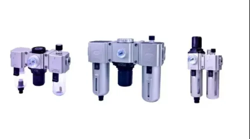
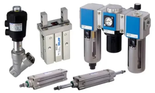
Hakimi Pneumatic & Hardware can help a Bangalore builder check these details against an Airtac model rather than matching only the compressor outlet thread.
Related product
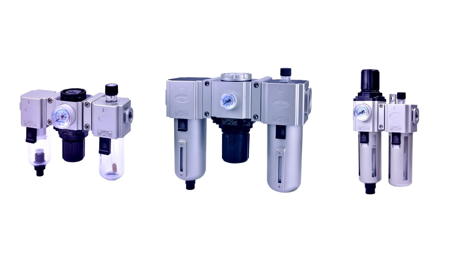 | Air Preparation Unit (FRL) Pneumatic FRL Air Preparation Units – Filter, Regulator, Lubricator Combo Ensure clean, regulated, and lubricated airflow with this trio of Pneumatic FRL Units. View product → |
Frequently asked questions
How do you choose a pneumatic FRL size for a machine build?
Start with peak simultaneous air demand from cylinders, grippers, valves and blow-off devices, then select an FRL that delivers that flow without excessive pressure drop.
Does cylinder bore determine the correct FRL size?
No. Bore determines cylinder displacement; FRL sizing depends on the total air volume consumed during the machine’s busiest cycle.
Is FRL port thread size the same as flow capacity?
No. Port thread size identifies the connection, while usable flow capacity depends on the internal passage, pressure conditions and pressure drop.
What should you check on an FRL datasheet?
Check rated flow conditions, inlet pressure, outlet pressure range, pressure-drop curve, filtration rating, drain type and maximum operating pressure.
Keywords