The value of a valve manifold depends on more than a 24VDC coil and an IP65 label. You will be able to judge the design by checking environmental protection, actuator demand, valve function, electrical compatibility, expansion plans, and the installation evidence supplied by the vendor.
Key takeaways
- IP65 resists dust and water jets, but not immersion or high-pressure washdown.
- Size manifold capacity from cylinder flow demand, not valve station count.
- Match valve architecture to each actuator’s exhaust, speed and fail-state needs.
- Verify 24VDC voltage, current, connectors and PLC outputs before commissioning.
What IP65 protects—and what the rating leaves exposed
IP65 protects against dust ingress and water jets, not immersion, hose-down pressure, or high-pressure washdown. Under IEC 60529, “6” means dust-tight and “5” means protection from water jets.
A product listing for a dc24v ip65 valve manifold for oem machines in bangalore does not prove that the complete installed assembly has this protection. Confirm whether the rating covers the coil, M12 connector, DIN plug, complete assembled manifold, or enclosure after installation.
1. Request the tested configuration, including cable glands, M12 connectors or DIN plugs, unused stations, manual overrides, exhaust ports, seals, and end covers. A loose connector, missing blanking plate, damaged seal, installation scratch, or exhaust path that admits contamination can reduce effective protection.
2. Recreate the machine’s exposure before approval. Record washdown pressure, spray direction, spray duration, cleaning chemicals, ambient temperature, and every risk of temporary submersion. Compare these conditions with the supplier’s IEC 60529 test evidence, not with a photograph or generic quotation.
3. Reject IP65 alone when water can pool around the manifold, spray arrives at high pressure, chemicals attack seals, or the exhaust draws contaminated air. Choose a higher-rated assembly or add a suitable enclosure when the machine faces immersion or high-pressure washdown; protect exhausts without restricting valve performance.
Size the manifold from the cylinders, not the station count
Station count cannot size a pneumatic valve manifold for OEM machines; simultaneous air demand and allowable pressure drop do. A compact rail with ten stations can starve before a four-station rail if its common inlet, exhaust, or FRL is undersized.
- Record each cylinder’s bore, rod diameter, stroke, target stroke speed, operating pressure, tubing inside diameter, tubing length, and required cycle time.
- Calculate extension volume as bore area × stroke. Calculate retraction volume as (bore area − rod area) × stroke.
- Divide each volume by its required movement time to obtain flow demand, then add the actuators that move simultaneously. Include tubing volume and leakage in the design margin.
A valve’s published figure may be nominal flow, effective area, Cv, or a test result at stated inlet and outlet pressures. Compare identical test conditions before selecting a larger valve; unlike figures do not prove higher machine capacity.
| Check | Compact rail | Separate routing |
|---|---|---|
| Inlet and FRL | Less tubing and labour | Easier independent supply |
| Exhaust and silencers | Shared passages can create back-pressure during rapid retraction | Less station interaction |
| Panel space | Smaller installation | Needs more mounting area |
Check the common inlet, supply tubing, manifold pressure drop, shared exhaust passages, silencers, and back-pressure. Confirm the valve pressure range, ambient temperature, vibration resistance, and available panel space.
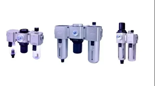
Control contamination at the inlet: water, compressor oil, pipe scale, and desiccant dust can stick spools or damage seals. Match filtration, regulation, and lubrication to the valve maker’s instructions.
Choose the valve architecture that matches each actuator
A manifold is worth choosing when repeated actuator layouts and tight panel space outweigh the risk of one shared failure; it is not automatically the right format for every valve.
Match function first: 2/2-way valves provide on/off isolation or flow control, 3/2-way valves operate single-acting cylinders, 5/2-way valves operate double-acting cylinders, and 5/3-way valves provide a defined centre condition.
| Architecture | Best fit | Main trade-off |
|---|---|---|
| Manifold | Repeated layouts, reduced wiring and mounting space | A shared seal, inlet, exhaust or connector can affect several stations |
| Individually wired valves | Physical separation, independent environmental protection or separate pressure zones | More wiring, tubing and mounting labour |
| Fieldbus valve island | High valve counts and networked diagnostics | Requires compatible protocol, power and commissioning |
| Remote I/O with separate valves | Distributed machines with local sensors and valves | More local hardware and network cabling |
| Single standalone solenoid | One isolated actuator or easy replacement | Poor fit for repeated layouts |
Do not treat catalogue families as interchangeable because both say 5/2 or 3/2. Verify port size; BSPP, BSPT or NPT thread; mounting pattern; coil width; pilot arrangement; supply and exhaust configuration; and manifold-base geometry. ISO 15407 and ISO 5599 identify specific interface families, not universal compatibility. Confirm common exhaust back-pressure and station order before release.
Prove the 24VDC electrical interface before commissioning
A 7.0W coil at 24VDC draws about 0.292A (7.0 ÷ 24). Compare that figure with the PLC output-channel rating, then add every coil that can energise together: four simultaneous coils require about 1.17A before indicator or interface loads.
Require the supplier to identify:
- Connector type, pinout, commoning arrangement, sourcing or sinking logic, and polarity requirements
- Coil voltage tolerance, duty cycle, indicator-LED current, and surge-suppression method
- Output fault diagnostics, manual override access, and exact replacement coil or valve
| Interface check | What to confirm | Failure if ignored |
|---|---|---|
| Sourcing output | PLC sources positive voltage to the coil | Valve will not energise with a sinking-only connection |
| Sinking output | PLC switches the return path | Incorrect commoning can short the output |
| Suppression | Coil or PLC interface contains flyback protection | Electrical noise or damaged outputs |
| Suppression timing | Measure release after de-energising | Protection can lengthen valve release and exhaust timing |
Nominal 24VDC does not define allowable variation. Obtain the coil’s specified voltage range, measure supply drop at the manifold under load, and verify emergency-stop isolation, response time, exhaust timing, output diagnostics, and recovery after power interruption.
For a dc24v solenoid valve manifold in bangalore, include duty cycle, ambient temperature, vibration, connector retention, and manual-override access in the OEM acceptance test. The electrical label alone proves compatibility with neither the PLC nor the machine cycle.
Make the buying decision on lifecycle evidence and expansion
The premium is justified when repeated layouts, high assembly labour, limited panel space, fewer tubes and wires, and standardised servicing save more over the machine’s life than the manifold costs. The trade-off is a shared failure: contamination, a common seal, connector, or manifold base fault can stop several actuators.
| Option | Lifecycle benefit | Main risk |
|---|---|---|
| Manifold | Faster assembly, compact panel, repeatable wiring and servicing | One common fault affects multiple stations |
| Separate valves | Isolation, independent replacement and different pressure zones | More tubing, wiring, mounting space and labour |
| Expandable manifold | Supports machine variants without replacing the rail | Inlet, exhaust, PLC or panel capacity can be exceeded |
Before approval, request:
- Station count, valve order, spare-station policy, expansion method, and the specified blanking plates, seals, and end covers for unused stations.
- Confirmation that future variants fit the released rail, with added stations staying within inlet, exhaust, PLC and panel capacity.
- A traceable part-number breakdown and datasheet stating valve function, port thread, flow metric and test conditions, pressure and temperature range, coil rating, connector IP rating, station order, replacement coils or valves, and installation restrictions.
Evaluate an IP65 pneumatic manifold supplier in Bangalore on this evidence and local replacement availability, not a photograph. Hakimi Pneumatic & Hardware can verify the exact Airtac configuration as a Bangalore wholesale source, but the OEM must test the installed assembly against its own plan.
Choose the manifold when layout repetition and space savings outweigh common-failure risk; choose separate valves when isolation or widely different conditions matter more.
Related products
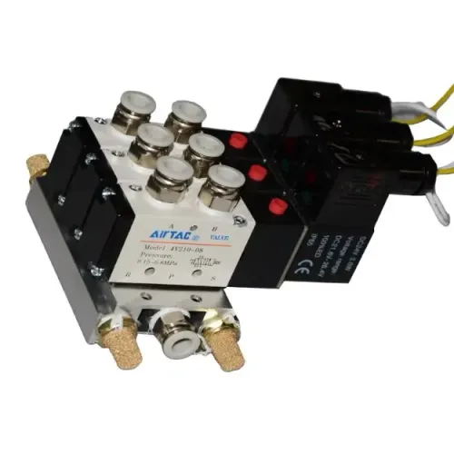
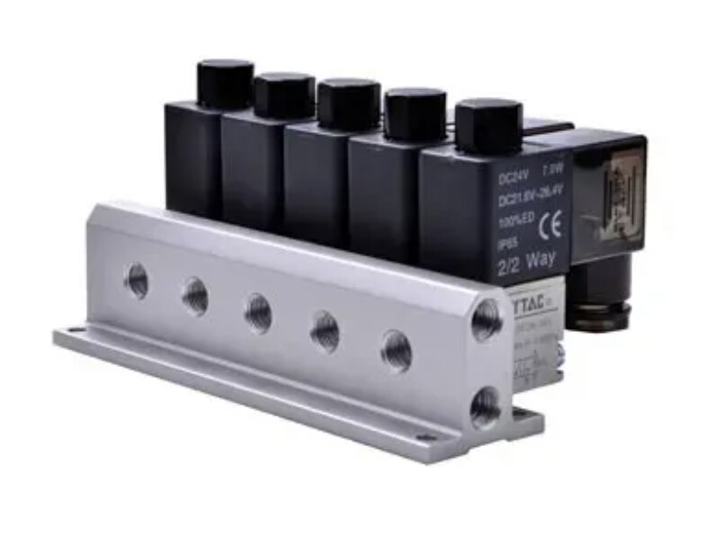
 | Solenoid Valve Manifold Pneumatic Solenoid Valve Manifold Assembly – DC24V, IP65 Engineered for precision and compact control, this Pneumatic Solenoid Valve Manifold Assembly features multiple 2/2-way solenoid valves mounted on a... View product → |
 | Solenoid Valve AIRTAC 4V210-08 Pneumatic Solenoid Valve – DC24V, 5-Port, Muffler Fitted The AIRTAC 4V210-08 is a high-performance 5-port solenoid valve designed for precise control of compressed air in industrial automation systems. View product → |
Frequently asked questions
What does IP65 protect on a valve manifold?
Under IEC 60529, IP65 means the enclosure is dust-tight and protected against water jets. It does not protect against immersion, hose-down pressure or high-pressure washdown.
How should you size a pneumatic valve manifold for OEM machines?
Calculate demand from each cylinder’s bore, stroke, cycle rate and operating pressure, then compare the required flow with the manifold and valve orifice capacity. Do not size it from station count alone.
Which valve architecture should you choose for each actuator?
Choose the valve arrangement according to the actuator’s required motion, exhaust path, speed control and safe state during power loss. Single-solenoid, double-solenoid, 3/2-way and 5/2-way valves serve different applications.
What must you verify before connecting a DC24V solenoid valve manifold?
Confirm the 24VDC nominal voltage, voltage tolerance, coil current, connector wiring, polarity requirements, suppression method and PLC output capacity before commissioning.
Keywords